
When we delve into the domain of digital electronics, one of the fundamental tools you will encounter is the truth table. A truth table is a mathematical table that illustrates the output of a logic gate or circuit for all possible input combinations. Its purpose is clear cut – it allows us to visualize the function of the circuit and predict its behavior for any given input scenario, thus facilitating the process of converting truth tables into boolean expressions. Creating one from a circuit might initially seem daunting, but in essence, it involves listing all possible input states and systematically computing the corresponding output states. This article aims to guide you through the process of constructing a truth table from any digital circuit, whether simple or complex, also touching upon how to derive a boolean expression from the truth table and eventually how such an expression can be implemented as a truth table to logic circuit.
Understanding Digital Circuits Basics
Before we can construct a truth table, or delve into how to read a truth table, we need to have a foundational understanding of digital circuits. At their core, digital circuits use binary signals to process and convey information, with each signal being either high (1) or low (0). These circuits are the building blocks of modern electronic devices, ranging from basic calculators to complex computer systems.
The most vital components in these circuits are logic gates. These are electronic devices that perform basic logical functions and are the glue that holds the digital world together. Each logic gate is designed to produce a specific output based on the inputs it receives. Common logic gates include:
- The AND gate, which outputs high only if all its inputs are high.
- The OR gate, which outputs high if at least one input is high.
Aside from facilitating how do truth tables work, logic gates orchestrate the flow of digital signals through a circuit, manifesting the operational blueprint to which the circuit adheres.
In addition to these, other essential gates are the NOT, NAND, NOR, XOR, and XNOR, each with its unique behavior in a digital circuit.
The relationship between a circuit’s inputs and outputs is what a truth table is designed to show in a clear and concise manner, unveiling the logic that drives digital computations. Learning how to read a truth table is therefore key in interpreting the outputs of various logic combinations.
The Role of Logic Gates in Truth Tables
To appreciate how truth tables are constructed, one should understand the logic gates at the heart of these circuits. We can categorize basic logic gates into the following:
- AND, which gives a high output (1) only when all inputs are high.
- OR, which delivers a high output when one or more inputs are high.
- NOT, which is a unary gate that inverts the input, thus a high input results in a low output and vice versa.
- NAND, which is the inverse of the AND gate, providing a low output only when all inputs are high.
- NOR, which is the OR gate’s inverse, giving a high output only when all inputs are low.
- XOR, the exclusive OR gate, outputs high when an odd number of inputs are high.
- XNOR, also known as the exclusive NOR, outputs high when the inputs are the same.
Understanding how these gates work is pivotal since each has a characteristic effect on the outcome depicted in the truth table. Grasping this concept is fundamental to both how do truth tables work and how these results can be extrapolated to design circuits.
Step-by-Step Guide to Creating a Truth Table
The methodology of constructing a truth table can be broken down into well-defined steps. These not only make it easier to visualize the functioning of digital circuits but also are instrumental when converting the tabulated data into workable circuit designs. Here’s a systematic approach:
- Identifying the variables involved in the circuit and preparing a list of all possible states for these variables.
- Recording these states in a structured format known as a truth table.
You commence by identifying variables and possible states. Approach this by looking at the circuit and noting down each input. It’s these various inputs, with their binary possibilities, that set the foundation for creating the truth table. For a circuit with more than one input, you need to list all possible combinations of these inputs. This number exponentially increases with the addition of more inputs (calculated as 2^n where ‘n’ is the number of inputs).
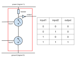
Given that, let’s consider a simple example with two variables, ‘A’ and ‘B’, in the table below:
| A (Input 1) | B (Input 2) |
|---|---|
| 0 | 0 |
| 0 | 1 |
| 1 | 0 |
| 1 | 1 |
This table lists all possible combinations for a two-input system. From here, you would calculate and fill in the outputs for each gate within the circuit, eventually completing the truth table. How do truth tables work in complex circuits? Much like our simple example, in more complex arrangements, inputs are tracked through various logic gate operations to derive the outputs, but more steps and careful tracking are required to handle the intricate combinations.
Next is about filling in the truth table template. Do this systematically by considering the effect of each logic gate in the circuit in sequence. Proceed by starting from the input end and methodically moving towards the output end, evaluating and documenting the results at each stage or gate. This organized progression ensures full coverage of the possibilities, reducing chances of error and clarifying the circuit’s logic before it’s turned from a truth table to logic circuit.
Following this structured method, the trial-and-error phase of digital design is significantly curtailed. You acquire a precise map of how the circuit will respond to various stimuli, a boon for anyone from hobbyists to professional engineers.
Practical Examples
Having mastered the basics of logic gates and the methodology to construct truth tables, let’s apply our knowledge through practical examples. Going through these will reinforce your understanding and offer insights into the practical aspects of designing and analyzing digital circuits.
Creating a truth table for a simple circuit
Imagine we have a basic circuit with two inputs (A and B) that feeds into an AND gate, and the output of this AND gate is connected to a NOT gate, the result of which is our final output (Y). Now, to create a truth table for this circuit, we will:
- List down all possible combinations of the inputs A and B. With two inputs, there are four combinations, as we’ve seen in the previous table.
- Determine the output at each stage of the circuit for each combination of inputs.
We proceed as follows for each combination:
- Evaluate the output of the AND gate first. This will be high (1) only if both inputs A and B are high.
- Next, take the output of the AND gate and determine the output of the NOT gate, which will simply invert the received input, turning a high into low and vice versa.
By documenting this for each input combination, we generate the truth table for this circuit:
| A (Input 1) | B (Input 2) | Output of AND gate | Y (Output of NOT gate) |
|---|---|---|---|
| 0 | 0 | 0 | 1 |
| 0 | 1 | 0 | 1 |
| 1 | 0 | 0 | 1 |
| 1 | 1 | 1 | 0 |
This table clearly delineates how our simple circuit behaves. It also serves as an excellent checkpoint before you physically build the circuit or simulate it using software tools.
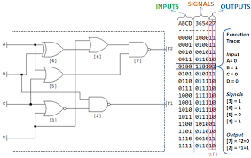
Complex circuit truth table walkthrough
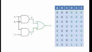
Next, let’s tackle a more complex circuit, where multiple gates are interconnected. Suppose we have a circuit with three inputs (A, B, and C) that are fed into various gates whose combined outputs provide a single output Y. Our approach would be methodical:
- Assign variables to inputs and list the possibilities. With three inputs, there are eight possible combinations.
- Evaluate each stage of the circuit systematically for all input combinations.
Here’s a straightforward step process to tackle the complexity:
- Divide the circuit into identifiable sections, each section containing a simple gate or a small group of gates that you can evaluate individually.
- Perform a truth table for each section and use this as an input for the next stage.
- Finally, merge these partial truth tables, following the logical connections from one stage to the next, until you reach the final output.
Each step can be validated against the known logic of every gate involved. By iterating through all input combinations, you can confidently plot the complete behavior of the complex circuit, thus ensuring that every potential eventuality is covered.
Troubleshooting Common Issues
With the basics in place, we can now address some of the frequently encountered issues when working with truth tables:
- Overlooking a combination: Ensure each possible input state is represented in your truth table.
- Misinterpreting gate functions: Double-check the characteristic table for each logic gate type.
- Cascading errors: Errors in early stages can propagate, so validate your results at each step.
- Complexity management: For complex circuits, break down the problem into manageable parts and tackle each sub-circuit independently before integrating.
By following these troubleshooting steps, you’ll greatly improve your accuracy when working with circuits and truth tables alike.
Conclusion
Having journeyed through the process of creating truth tables from circuits, we can appreciate their value in the realm of digital electronics. Truth tables serve as the blueprint for understanding and predicting the outcomes of various digital logic designs. By constructing truth tables, we gain the ability to convert these logical representations into Boolean expressions, paving the way for truth table to logic circuit conversion.
Fundamental to this process is comprehending how do truth tables work, the role of logic gates, and the systematic approach in evaluating digital circuits of varying complexity. It is through hands-on practice and patient analysis that one can assure proficiency in creating and using truth tables. Be sure to utilize additional resources and practical exercises to reinforce your understanding.
FAQs
- What is the importance of a truth table in digital circuits?
Truth tables are crucial in digital circuit design as they provide a reliable method for visualizing and verifying the function of a circuit. By mapping out all possible input combinations and their corresponding outputs, engineers and students alike can predict and understand the behavior of logic gates and circuits without physically building or testing them. - How can I convert a truth table into a Boolean expression?
To convert a truth table into a Boolean expression, identify the input combinations that result in a high output. Write a minterm (an AND combination of inputs) for each of these cases and then combine them with OR operations. This will yield the sum-of-products Boolean expression that represents the truth table. - Can you create a truth table for any digital circuit?
Yes, you can create a truth table for any digital circuit, but the process becomes more complex with the increase in the number of inputs and logic gates. It requires meticulousness to ensure that all possible states and logic gate interactions are considered. - Are there tools available to simplify the creation of truth tables for complex circuits?
Yes, various software tools are designed to assist in creating truth tables, simulating circuits, and checking logic. These tools often include features that automatically generate truth tables from a given logic circuit diagram, greatly simplifying the process for complex circuits. - What are the most common mistakes when constructing truth tables?
Common mistakes include missing combinations of inputs, incorrect application of logic gate functions, and calculation errors when filling in table values. To prevent these errors, double-check your work and consider using digital circuit simulators for validation.